Writing a Chip8 emulator in C++ part 3
The emulator can be thought of as Lego blocks that are supposed to fit together to make a cohesive whole. Importantly, I wanted it to be platform agnostic so that I could port the code to different platforms without having to re-write entire core modules. The following, at minimum, need to be platform independent:
- Some way to create a emulator window.
- Render graphics whether they be text, sprite, GUI elements or individual pixels.
- Sound output using a streaming buffer of sorts.
- Handle keyboard and mouse inputs.
Luckily, there are excellent third party libraries available that can be used to do *all* of the above.
The first and perhaps one of the most popular is Simple Direct media Layer (SDL 2 more precisely). As the name suggests SDL is an abstraction layer between the hardware/OS and our program. Instead of worrying about Mac or Windows implementation of sound and graphics, I can just call SDL and let it do the leg work of working with the OS to get the work done.
SDL allows us to write to a frame buffer (basically a 2d array of memory that can be mapped to the screen), read and write to a streaming audio buffer (an array of memory that holds raw sound values), get OS events for keyboard event and window events. It takes care of things in the background so that we see things on screen, hear audio output and handle user inputs.
That took care of most of the things on my list! I still had the GUI to take care of and for that I wanted to leverage another excellent library called Dear IMGUI. It allows us to create menu’s, buttons, drop-downs and other GUI elements on any platform, in a simple easy to use manner.
Since the GUI system is entirely optional for the purpose of writing the actual emulator, I won’t go into details of it here. If you’re interested in knowing more about it, you can take a look at the code in main.cpp.
Let’s wade into the setting up the emulator window using SDL then.
Setting up the window
| |
That initializes an emulator window with enough space for everything I needed (including the GUI). The depth and stencil buffer aren’t really things I need for my particular setup but I’ve kept them in for completeness.
Notice that the above returns a window handle reference. I need this for IMGUI later on, but it may also be required for anything else that requires a context to my window.
With that done, I can actually start tackling the Chip 8 emulation. For this, I will create a separate class called, predictably, Chip8 that takes care of the actual emulation.
The emulation core
Decoding the 2 byte Chip 8 instruction requires masking and manipulating the bits to extract the code and the data. Because the instructions only actually involve 12 bits of the 16 bits available, I needed to mask out the appropriate bits to decode the entire instruction. To make life easier, I defined some macros that will do the manipulation:
| |
An array of 4096 unsigned bytes is used as the memory for chip 8:
uint8_t Memory[4096];
Using the description of the registers for chip 8 from the technical docs, they can be defined like so:
| |
With those defined, I can start decoding instructions! Presuming PC points to 0x200, the instruction can be fetched this way:
| |
First, the opcode is correctly read in Big-endian order into a 16 bit variable. The PC is also incremented by 2 in preparation for the next instruction.
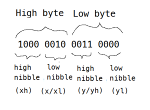
Every instruction can be broken down into one or a combination of the forms above. For eg, from Cowgod’s docs, the instruction for **LD V_x_, V_y_** is stored in memory as **8xy** (hex) - where x and y refer to any two of the general purpose registers.
So, to decode an opcode to see if it’s the above instruction involves examining the high nibble of the high byte (xh) and see if it’s a 0x8, if so the lowest nibble of the lowest byte (n) should also be 0 for it to be a valid **LD V_x_, V_y_** instruction. If both the conditions are satisfied we can proceed to get the two registers involved by using the x and y values from the lower nibble of the high byte (xl) and higher nibble of the low byte (yl). The figure below shows how the masks work:
Opcode: 0x8230
With the opcode decoded I can check which instruction it corresponds to via a switch statement. There are other fancy ways of doing this via look up tables and function pointers, but for Chip 8 a switch statement is good enough. This how the switch looks like for LD Vx, Vy:
| |
Every instruction can be decoded this way. The LD Vx, Vy is admittedly a simple one, involving copying the contents of the Vy register to Vx.
There are a couple of interesting instructions that feature an undocumented behavior. For eg, the SHR Vx and SHL Vx instructions which should simply shift Vx right or left respectively by 1 bit after storing the least significant bit (LSB) of Vx in VF. The code would look like this for SHR Vx:
| |
However, it appears that originally the instruction was meant to assign the shifted value of Vy to the Vx register instead, which is a totally different thing:
| |
Since the operation is on the Vy register, the Flag register takes its value from Vy instead of Vx. Also, even though Vx takes the value of the shifted Vy, the latter itself is unaffected!
The implications are that if a program is written expecting the behavior of shift to be in a particular way, the nature of the shift instruction can cause unwanted outcomes. Now, one can simply implement the most common behavior and be done with it, but it’s easy enough to support both behaviors by way of an option in the emulator, so that’s what I will do. This option can be exposed via a command line argument or a GUI check box that the user can toggle to control the behavior. This will map to a boolean in the emulator core that decides which behavior to use:
| |
Next I take a look at how to draw stuff on the screen. This is a bit more involved so that’s the subject for the next part in this series.