Writing a Chip8 emulator in C++ Part 2
The Chip 8 is a actually an interpreted language running on a virtual machine. Cowgod’s page describes both in great detail. I will not go into the details as already described there, I will instead focus on how I went about writing an emulator based on the specifications. The critical bits of info can be distilled as follows:
- The Chip 8 has 4k of addressable memory. The first 512 bytes are reserved (originally for the interpreter) and should not be used.
- There are 16 8-bit registers numbered, traditionally, as V0, V1 … to VF (hexadecimal). VF is a special flag register that’s modified by certain instructions.
- Chip 8 also employs two special 8 bit registers that act as a general delay timer (DT) and Sound timer (ST). Both are decremented at rate of 60HZ when they are non-zero. A sound tone is emitted in the case of ST whenever it’s decremented.
- The display is monochrome and of 64x32 pixel resolution. The origin (0,0) is at the top left.
- There are 36 instructions in the Chip 8 language. All of them are 2 bytes long and are of the Big Endian form.
- Interestingly for a valid instruction, it’s first byte should be at an even address.
- The keyboard is very simple and consists of the Hexadecimal numbers from 0 to F.
- Two pseudo-registers PC and SP are not available to programs but control the execution of Chip 8. PC is a 16 bit register that holds the memory address of the current instruction. SP is a 8 bit register that points to an array of 16 16 bit values (memory addresses).
That’s it really. Compared to a machine like the NES or the ZX Spectrum, the Chip 8 is actually a far simpler machine to emulate given the above specs.
Designing the emulator
At its core an emulator steps through memory, decoding instructions (if they are valid) and taking an action based on what the instruction is supposed to do. The instructions may require the CPU to do arithmetic operations, act on certain conditions, copy blocks of data, output to the screen, play sound, handle input et al. The display, sound and handling of inputs require interfacing with external hardware components, so it makes sense to separate them from each other, like so:
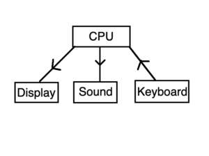
In general, the display, sound and keyboard are all I/O devices and will be abstracted in a better way when writing a more advanced emulator. But for the purpose of Chip 8 I wanted to keep things simple and not go overboard with creating classes out of every single thing.
I imagined the emulation steps as follows:
- Initialize display, sound and cpu (registers and memory).
- Handle any events (window, keyboard).
- Fetch the instruction at PC (points 0x200 at start).
- Decode the instruction. Update PC.
- If DT > 0, then DT = DT - 1.
- If ST > 0, then output a tone, ST = ST - 1.
- Update display at 60FPS.
- Repeat Steps 2 to 7 (the emulation loop)
However, since I decided to add some “features” to the emulator, the above steps will work in conjunction with the GUI and debugger as well.
The good thing about Chip 8 is that I don’t have to worry about instruction timings (all of them take 1 cycle) or any sort of syncing between the raster and CPU or memory as can happen in more advanced systems. Effectively the display can be decoupled from the emulation.
Right. Now that I knew what I had to do (even if at a high level), I could go about actually implementing all the stuff I outlined above. And that’s in Part 3.