Writing a Chip8 emulator in C++ Part 4
The instruction that deals with drawing sprites on screen is the DRW Vx, Vy, n or Dxyn in hex. It breaks down as follows:
Each sprite is made made of 8 bits of which only the upper half (the high nibble) is used. To draw the sprite, the I register is set to the start location of the sprite data to be drawn on screen. Any two registers Vx and Vy are chosen to hold the screen co-ordinates that the sprite should be drawn to. The n is the number of bytes that comprise the sprite data. For eg, in main.cpp I use some Chip 8 instructions to draw the word “READY” on boot up. The letter R is made up this way:
| |
Note that the lower half of the byte data is 0 since I’m using only a 4 bit wide char (details in part 5). To output the above to location 10, 10, presuming the I register is set to 0x21a (the start of sprite data), and that V2 and V3 hold the X and Y co-ordinates (i.e the value 10), the draw instruction will be: 0xD235.
Simple enough. Decoding such an instruction is a bit more involved though. Quoting from Cowgod’s description of it:
The interpreter reads n bytes from memory, starting at the address stored in I. These bytes are then displayed as sprites on screen at coordinates (Vx, Vy). Sprites are XORed onto the existing screen. If this causes any pixels to be erased, VF is set to 1, otherwise it is set to 0. If the sprite is positioned so part of it is outside the coordinates of the display, it wraps around to the opposite side of the screen
Whew! It seems to be a bit tricky at first but it’s pretty clear what needs to be done. A bit of code will help illustrate the steps:
| |
There are two loops involved here. One which steps through the number of bytes to draw (n), and the other that steps across the individual bits per byte of data.
The first thing to do is reset the Flag register, since I need it to signal if any pixel is erased.
Next I start stepping through every byte of sprite data. So if n = 5, then I need to loop through 5 bytes of sprite data.
Since the I register points to the start of the sprite data, the current sprite data is fetched by simply indexing to it via Memory[I + i], where i = {0, 1, 2, 3, 4}.
The Y co-ordinate is increased by 1 as we step through the sprite data too, and wrapping around can be achieved by simply using the MOD operator against the screen height (32). So, (Vy + i) % 32 will automatically wrap to (0+i) if (Vy + i) >= 32. A similar technique is used to wrap for the X co-ordinate as I’ll explain shortly.
The next loop will step through the 8 bits in the current byte and put them across the X co-ordinate.
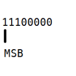
The bits for the sprite data are read from left to right as they are put down across the screen column. The way I do it is to mask the MSB (Most Significant Bit) of the high byte like so:
sprite & 0x80
This will give either 10000000 (128 decimal or 0x80 hex) or 00000000 in binary depending on whether the MSB is set or not.
Since I’m only interested in the actual bit as “truthy” value (0 or 1), I need to shift the bits right by 7 to end up with 00000001 or 00000000 binary, which is just 1 or 0 decimal.
Note that shifting the value when it’s actually 0 is redundant but shifting is a fast operation and is faster than checking for 0 and not doing the shift (because branching is expensive)! The final outcome of the above looks like this:
b = (sprite & 0x80) >> 7;
Similar to how we calculated the Y and wrapped it we can do the same for X, by (Vx + f) % 64, where f = {0, 1, 2, 3, 4, 5, 6, 7}
Now that I have the correct row and column co-ordinate as well as whether to set the pixel at this location or not, I can update the byte at the display memory. The display memory is just an array of 64x32 bytes (well actually unsigned int32 but holding only byte worth of information) which map to every pixel on the screen. This is a one dimensional array. The screen as represented by the row and column co-ordinate is, however, a 2D dimensional array. Mapping the row and column co-ordinates to an offset into the one-dimensional array can be done simply enough by using this formula:
offset = row * 64 + col
To set the byte (which represents a pixel) at the display offset, I simply check if the bit mask is a 1 (set), which is the only operation that will affect a pixel on screen (in the case of 0, the previous pixel at the location is not affected). If writing to the screen, and there is a previously set pixel at that location I need to set the Flag register accordingly (this can be used by games as a means to detect collision), which is done by the following:
| |
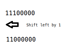
Finally, I can move on to the next bit in sequence by shifting the sprite byte left by 1 so that the next bit becomes the MSB and the old MSB is dropped off - we don’t need it anymore since we are done with it anyway:
sprite «= 1;
And that’s the sprite drawing routine done and dusted. Well not quite. I actually didn’t write to the graphics hardware but to a software display memory. I need to upload/blit the information to an OpenGL texture which will then be mapped to a quad and then drawn on the screen.
To do this, I created a CTexture class, which has the update and render methods to achieve the above. I won’t go into those details as they are specific to OpenGL but the code is in CTexture.cpp, if you’re interested.
That concludes most of the core emulation and the point of this series of articles. I also added sound and input handling to the emulation because things wouldn’t be as much fun without them. However, they aren’t as interesting to implement or talk about. Again, if you’re interested in the technical aspects of those, the files Chip8Sound.cpp and main.cpp will be of interest.
There is one more aspect of Chip8 that may of interest though, and that is writing a simple program using the Chip8 instructions. I go over this in the last part of this series, in part 5.